All posts by Cody Whisenhunt, President, BCS Switchgear

BCS Switchgear is an industry leader in new and obsolete electrical control and distribution equipment. Since 1997, BCS has been servicing customers to extend electrical life of low and medium voltage electrical power equipment. Cody can be reached by email: [email protected]

Replace or Keep Your Existing Switchgear?

by Jim Hardy, BCS Switchgear, Inc.


“When customers talk to us about replacing their existing switchgear, they are looking for an economic basis for making a decision to keep their existing switchgear vs. replacing it.”


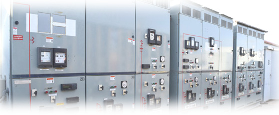
Replacing Switchgear

The major concerns engineers and management have are based on safety, reliability and costs.

Most companies use a financial model to decide which projects to proceed with.  We are suggesting that keeping the existing switchgear in service be treated as a new project, then comparing the costs.


Keeping existing equipment

Westinghouse Type DH Circuit Breaker
Westinghouse Type DH  Breaker

✔ Low and medium voltage switchgear (including circuit breakers and contactors) are approaching or beyond their expected useful life.

✔ Employee safety is reduced due to original product design not meeting current standards and improper lubrication and maintenance over time.

✔ Arc chutes of some old contactors and circuit breakers contain asbestos

✔ Increasing plant risk of forced outages

✔ Increasing difficulty locating replacement parts

✔ Increasing maintenance expense as more parts require replacement? Not sure about this one

In financial terms, the choice between keeping the existing equipment and replacement is to determine which one has the highest net present value (NPV).  There are a number of other financial models which could be applied, but they all have the same problem:

Calculating a value for replacement is fairly straightforward (hoping no surprises come up during the project!), but there a lot of variables in calculating the value of keeping the equipment.  Or assumptions might have to be made that might not be valid.


Replacing Equipment

✔ Increased safety particularly with regard to NFPA70e

✔ Reduced maintenance cost

✔ Opportunity to improve location or change the operating environment at some facilities

✔ Total cost of switchgear including installation and downtime


For example:
General Electric MagnaBlast Breaker

Will the price and availability of parts be stable over time?
Will the cost of downtime be constant?
What are the worst case risks associated with asbestos?
Increased expenses caused by changes in codes and standards?

We believe that  evaluating the option of keeping the switchgear, including the risks, will show that keeping the existing is a more expensive option than it may first appear to be.

Also, there are upgrade options that replace the circuit breakers and contactors without replacing the switchgear.  This could reduce the risks of keeping the switchgear and reduce the costs of replacing and installing new switchgear.


You can see examples on our websitewww.bcsswitchgear.com
Or email us at : [email protected]

Testing Low Voltage Switchgear

Methods for Testing Low Voltage Circuit Breakers

5.0   TESTING

5.1      LOW VOLTAGE CIRCUIT BREAKER TEST DATA SHEET

A Low Voltage Circuit Breaker Data Sheet should be filled out on every rebuilt circuit breaker. Test Data Sheets need to be completely filled out, and in particular circuit breaker name plate data, job number, curve specs, test results, date and technician name. If a technician has a question on the Low Voltage Circuit Data Sheet or question on how to perform a test then he should consult his/her supervisor.

5.2      MEGGER INSULATION TESTING

Megger Insulation Test – This test is required on all Low Voltage Circuit Breakers. This test is designed to insure that the breaker has adequate insulation. Test results can vary depending on weather conditions, but in most cases a test result of 100 mega ohms or higher is satisfactory for a rebuilt 480V circuit breaker. Test should be conducted from each phase to phase, phase to ground, and line to load. These test results should be recorded on the Low Voltage Circuit Breaker Data Sheet and attached to the job sheet.

5.3      CONTACT RESISTANCE TEST

Contact Resistance Test (Ductor Test) – This test is required on all low voltage circuit breakers and designed to insure that the circuit breaker has solid and equal contact surfaces on each phase. Compare resistance to adjacent poles and similar breakers. Investigate any deviations of more than twenty percent (20%).

5.4      ELECTRICALLY OPERATED BREAKERS

Electrically operated circuit breakers should be tested by means of applying voltage at the secondary disconnects and charging the circuit breaker charging motor (if stored energy mechanism), closing the circuit breaker from the secondary disconnects, and tripping the circuit breaker from the secondary disconnects. Verify operation of the Y relay. Also test any auxiliary contact circuits, under voltage devices, and bell alarms from the secondary disconnects. Test the blown fuse device on fused breakers.

5.5      HIGH CURRENT INJECTION TESTING

High Current Injection Test – This test is required on all Low Voltage Circuit Breakers. This test insures the reliability of the circuit breakers trip units. Each circuit breaker’s trip units should function within a specified time frame at a specific overload. It is customary to test a circuit breaker’s long time function at 300% of the breakers normal load rating and short time function at 150% of its overload rating. Instantaneous is determined by increasing the current level on the test set, using the run-up or pulse method, and injecting momentary current until the breaker trips. Clearing time should be within 20% of determined instantaneous setting. Determine ground fault time delay by primary current injection at 150% if applicable. Each manufacturer provides time current characteristic curves so as to determine if a circuit breaker’s trip units are operating as designed. Check the manufacturer’s curves for the specific circuit breaker being tested and record this information on the Low Voltage Circuit Breaker Data Sheet. Each circuit breaker should be tested on all functions and on all three phases.

5.6      CELL RACK-IN TEST

Rack-in Test – This test is required on all Low Voltage Circuit Breakers. This test insures the ability of the circuit breakers to be installed into the switchgear they were designed for. This test also insures the operability of all safety interlocks. The circuit breaker will be racked into the cubicle and various tests performed at each step in the racking process. Various factory tools and rails are also tested for compatibility.


5.7      QC INSPECTION

Initial and date the Process Control Form. Get inspector to initial and date the Process Control Form for testing.